Sample text
-
0769-38866368


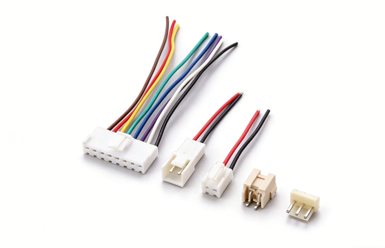
Industrial Equipment Wire Harness Connection Methods
We are also known as connectors or plugs. Their function is to link two active components, serving as a means for transmitting electrical current and signals. Depending on the application and environment, connectors come in various models, but regardless of the type, they must ensure smooth and reliable transmission of electrical signals. As application environments evolve, connectors have developed multiple connection methods to better adapt to on-site conditions and guarantee stable signal transmission. Below are several common connector connection methods:

- Threaded Connection
This is a traditional connection method, now relatively uncommon. It is used in environments with larger components or strong vibrations. The advantage of this connection type is its high reliability, as it secures cables through the friction of nut gears. Adding a lockwire to prevent loosening further enhances its effectiveness. The downside is that disassembly is slow, as it requires carefully unscrewing the threads, which is time-consuming. - Bayonet Connection
This is a currently popular connection method that allows for quick connection and disconnection. It is commonly used for linking two simple electrical components. Connectors using bayonet connections are marked with the correct locking direction at the coupling point. Users can check whether the connection is fully secured by observing the small holes on the side of the connector nut. - Push-Pull Connection
The push-pull connection is a widely used method. Connecting and disconnecting the plug and socket involves horizontal movement, without the need for twisting or rotation, allowing for quick connection and separation. Common push-pull structures include ball and pin types. This method eliminates the need for traditional mechanical locking mechanisms, making it difficult to disengage the connector once it is mistakenly inserted. - Cabinet Connection
This is an electrical connection method based on blind mating to equipment near the frame. This approach allows electrical devices to be made very compact and lightweight, with each unit operating independently, making maintenance easier and reliability higher. Since operators cannot visually perceive the connection status, precise positioning devices must be used to ensure successful connections. Floating contacts or spring designs are often employed to guarantee proper alignment. - Soldered Connection
Soldered connection refers to the formation of a continuous metal layer between the solder and the welded surface. Therefore, the prerequisite for connectors is solderability. Common platings for connector solder ends include tin alloys, silver, and gold. Reed-type contact pairs often feature solder tabs, punched-eye solder tabs, or notched solder tabs, while pin-type contact pairs typically have drilled arc notches. - Insulation Displacement Connection (IDC)
Also known as insulation displacement connection, this method offers high reliability, low cost, and ease of use. It is widely used in connectors for the printed circuit board industry. It is suitable for interconnecting ribbon cables. During connection, there is no need to puncture the cable’s insulation layer. Instead, the “U”-shaped contact spring tips of the connector pierce the insulation layer, allowing the cable conductor to slide into the connector’s groove and become secured, ensuring a tight contact between the cable and the connector.